
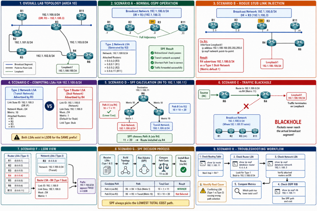
One of the most vital control-plane concepts to master is how OSPF’s Shortest Path First (SPF) algorithm evaluates candidate links during Dijkstra’s tree calculation.
It’s easy to assume that OSPF will naturally “prefer” a real multi-access segment over a loopback interface, or that it will detect conflicting subnet advertisements and throw an error. However, SPF is purely mathematical: if two intra-area routes exist for the same prefix, SPF chooses the path with the lowest cumulative metric—period.
In this post, we will break down a classic CCIE troubleshooting scenario: how a Loopback interface misconfigured with ip ospf network point-to-point injects a conflicting Type 1 Stub Link into the Link-State Database (LSDB), overrides a legitimate Type 2 Transit Network, and blackholes traffic.
The Base Topology
Consider the following Area 10 OSPF network:
OSPF LSA Fundamentals: Transit vs. Stub Links
To understand the conflict, we must review how OSPF represents multi-access networks versus leaf/stub subnets inside the LSDB:
Type 1 Router LSA: Generated by every router to describe its directly connected links, link types, metrics, and neighbors within an area.
Type 2 Network LSA: Generated only by the Designated Router (DR) on a multi-access (broadcast/NBMA) segment. It lists the subnet mask and all fully adjacent Attached Routers on that segment.
Bidirectional Reachability Rule
For SPF to include a Transit Link in the Shortest Path Tree, it requires a two-way validation check:
If a router claims a transit connection to a DR, but the DR’s Type 2 LSA does not list that router’s Router ID under Attached Router, SPF prunes that transit link from the tree.
Scenario A: Valid Multi-Access Segment (The Normal State)
On the top segment (192.1.100.0/24), R3 acts as the Designated Router (192.1.100.3). R1, R2, R3, and R11 are all fully adjacent across the segment.
LSDB Representation
Type 1 LSAs (R1, R2, R3, R11): Each router advertises a Transit Link pointing to DR IP
192.1.100.3with a metric of10.Type 2 LSA (Generated by R3):

Suppose an engineer configures a loopback interface on R4 to test host connectivity using
192.1.100.100/24, and adds ip ospf network point-to-point:
Note on OSPF Loopbacks: By default, OSPF advertises loopback interfaces as
/32 host routes. Overriding the network type with ip ospf network point-to-point forces OSPF to advertise the actual configured subnet mask (/24) as a Stub Network in R4’s Type 1 LSA.What Appears in the LSDB
Now, Area 10 contains two competing Intra-Area (O) representations for 192.1.100.0/24:
1. R4’s Type 1 LSA:
2. R3’s Type 2 LSA: Still lists 192.1.100.0/24 as a transit network with attached routers 0.0.0.3, 0.0.0.1, 0.0.0.2, and 0.0.0.11. (R4 is missing!)
How SPF Resolves the Conflict: The Metric Battle
$$\text{Path A (via R4): } \text{Cost}(R6 \rightarrow R4) + \text{Loopback Metric} = 10 + 1 = \mathbf{11}$$
$$\text{Path B (via R3): } \text{Cost}(R6 \rightarrow R3) + \text{Transit Metric} = 10 + 10 = \mathbf{20}$$
The Routing Table Outcome on R6
Because $11 < 20$, R6 installs the path via R4 into its routing table:

The Impact: Any packet sent from R6 to hosts on the broadcast segment (e.g., 192.1.100.1 or 192.1.100.11) is forwarded to R4, which drops or accepts the traffic locally on its loopback. The broadcast segment is completely blackholed for R6!
CCIE Troubleshooting Diagnostic Workflow
When encountering a reachability failure despite a valid OSPF route being present in the routing table, follow this three-step workflow:
Remediation Strategies
Depending on lab constraints, there are three primary ways to resolve this overlap:
1. Remove the Network Type Override (Standard Fix)
If Loopback 1 on R4 was intended to be a host testing interface, remove ip ospf network point-to-point:
R4(config)# interface Loopback1
R4(config-if)# no ip ospf network point-to-point
Effect: OSPF reverts to advertising Loopback 1 as a
/32host route (192.1.100.100/32).Result: Longest-prefix match directs traffic for
.100to R4, while general/24traffic correctly routes to the broadcast segment via R3.
2. Fix the Interface IP Addressing
If R4 was accidentally assigned an IP from an active segment, re-address the loopback:
3. Manipulate the OSPF Metric
If topology/IP changes are restricted by exam prompt requirements, increase R4’s loopback cost so the DR path wins the SPF calculation:
New Path A Metric: $10 + 50 = \mathbf{60}$
Path B Metric: $10 + 10 = \mathbf{20}$
Result: $20 < 60$; R6 reinstalls the DR as the next-hop for
192.1.100.0/24.
Summary Checklist for the CCIE Lab
[ ] Intra-area path selection is dictated purely by cumulative metric cost, regardless of whether a prefix originates from a Type 1 or Type 2 LSA.
[ ] Type 2 Network LSAs require a valid bidirectional backlink inside the attached routers’ Type 1 LSAs.
[ ]
ip ospf network point-to-pointon a Loopback forces OSPF to advertise the full configured prefix as a Stub link instead of a/32host route.[ ] Always verify
show ip ospf database network <DR_IP>using the DR’s IP address, not the network subnet address.